A Pole Does Not Fail at Random: Only Three Mechanisms
A steel lighting pole does not collapse suddenly or for countless reasons; when an actual field failure is investigated, it can almost always be traced to one of three specific mechanisms: corrosion of the steel at the ground-line zone until the section weakens, initiation of a fatigue crack at a weld whose stress is cycled repeatedly by wind, or movement in the foundation that transfers load into the pole in a way it was never designed for. These three mechanisms are not accidents; each is a physical process with a known point of initiation and a traceable path of progression, which is precisely why each can be prevented. Whoever understands how a pole dies knows exactly where to concentrate the design, manufacturing and installation effort, instead of spreading concern evenly across the whole product.
This guide differs fundamentally in angle from the guide on pole maintenance and extending service life: that one addresses what the owner does after delivery — the inspection schedule, re-torquing to specification, local repair — whereas this guide addresses the mechanism itself: why failure begins where it begins, and how each of the three failure mechanisms is closed off at the design, manufacturing and installation stage before the pole ever reaches the site. Maintenance reveals the early sign and delays the end, but it cannot cure a defect born with the pole. True prevention precedes maintenance and happens in the factory and in the foundation pit, and that is the subject of this guide.
Responsibility for these three mechanisms is distributed across three successive stages, not a single party: design fixes the section, the weld details and the foundation dimensions; manufacture executes the galvanizing and welding at the quality that actually protects the section; and installation casts the foundation and sets the bolts on site. A failure at any stage opens the door to one of the three mechanisms even if the other two are done well, which is why the safety of a pole is not measured by its manufacturing quality alone but by the soundness of the whole chain. The purpose of decomposing the mechanisms here is to let the buyer address a precise question to each stage rather than settle for a general specification of the finished product.
The First Mechanism: Base Corrosion at the Ground Line
The most aggressive environment along the length of the pole is not the sun-exposed top but the narrow band at the ground line: the zone extending from just above ground level to just below it. Here every corrosion driver converges at once: trapped moisture that does not dry quickly, sufficient oxygen to feed the reaction, salts and chlorides dissolved in the soil or in irrigation and wash water, and the wet-dry cycling that concentrates salts at the surface. A partially buried steel section behaves as a natural corrosion cell: the part immersed in damp, poorly aerated soil becomes an anode that corrodes preferentially against the aerated part above it. The result is that the pole begins to waste away, inside and out, at the base neck while the section above appears entirely sound.
The danger of this mechanism is that it is both hidden and accelerating. Hidden because the most severe corrosion occurs at or below the ground line where a passing eye cannot see it, so it advances for years without being noticed. Accelerating because the loss of section at the base occurs precisely where the bending moment produced by wind is at its maximum along the pole; the base is the structurally critical section and is at the same time the section most exposed to corrosion. When maximum stress meets minimum remaining section, failure becomes a matter of time. For this reason base corrosion is not treated as a cosmetic issue but as a direct structural threat, and the heaviest lines of defence in the protection system are directed at it.
Preventing Base Corrosion: Galvanizing Is a System, Not a Cosmetic Layer
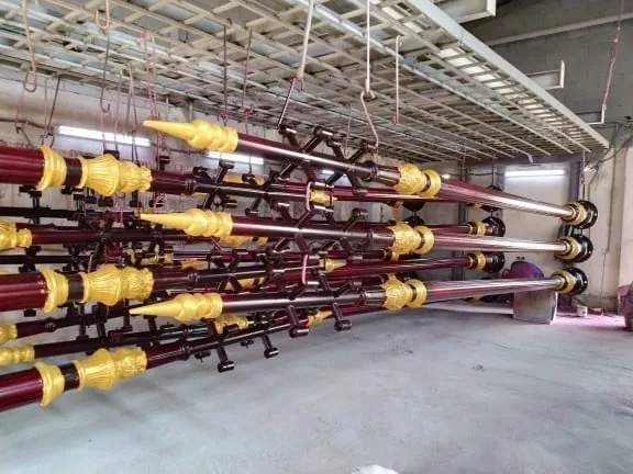
The first line of defence against base corrosion is hot-dip galvanizing to ISO 1461: the complete pole is immersed in molten zinc so that a metallurgically bonded zinc-iron alloy layer forms over both the outer and inner surfaces, including the inside of the tube wall, which cannot be coated after assembly. Galvanizing protects in two coupled ways: a physical barrier that isolates the steel from moisture, and cathodic protection in which the zinc gives up itself first and is consumed locally so the steel stays sound even where it is exposed by a scratch or gash in the layer at the ground line. It is precisely this last property that makes galvanizing suited to the zone most exposed to abrasion against the soil and to gashing, and the achieved layer thickness is verified by measurement to the method corresponding to ASTM A123.
The mistake that leads to early failure at this zone is settling for powder coating as the corrosion-protection system. Electrostatic powder coating is an organic layer that serves colour and appearance and adds a supplementary barrier, but it does not carry the chemical load alone at the ground line: the moment a scratch or porosity exposes the steel, rust begins at the point of damage, and because the coating gives the exposed steel no cathodic protection, corrosion creeps beneath the edges of the adjacent intact layer, lifting it and widening the wound. The system that closes this mechanism is galvanizing as the protection base, then coating over it for colour when required (a duplex system), not coating as a substitute for galvanizing. This is completed by a design detail that prevents water entrapment: drainage openings at the bottom of the pole, and a door detail that does not allow water to collect inside the cavity at the base.
The Second Mechanism: Fatigue and Cracking at Welds
The second mechanism is subtler than corrosion and more dangerous because it is purely structural: fatigue. The pole is not under a static load; the wind pushes it and it oscillates, and every gust and vortex produces a stress cycle that reverses and returns. With the repetition of millions of cycles over the years, a hairline crack may initiate at a stress-concentration point and then grow cycle by cycle until it crosses the section, and failure may occur at a stress level far below the yield stress the steel would sustain under a static load. The danger is that fatigue is not preceded by an obvious deformation that warns of it, as yield failure is; the crack advances silently until the last moment, which is why it is classed among the most dangerous pole-failure mechanisms and the hardest to detect.
For this reason the Saudi Building Code SBC 301 and the EN 40 standard for lighting columns treat wind as a dynamic load, not merely a static one. It is not enough for the pole to withstand the peak wind force once; it must withstand its cyclic repetition throughout the design life without a fatigue crack initiating. This obliges the designer to consider the stress range at the critical details, not the peak stress alone, and to select weld details and section dimensions that keep the cyclic stress range below the permissible fatigue limit. Whoever designs the pole for the static load alone may produce a pole that passes the peak-strength check and then fails by fatigue years later.
The key to understanding fatigue is that its resistance is not measured by the strength of the steel but by the connection detail itself; two connections of the same steel may differ greatly in fatigue life depending on the weld shape and the sharpness of the geometric transition at it. Codes therefore classify structural details into categories by their susceptibility to fatigue, and the smoother the transition and the lower the stress concentration, the longer the life at the same stress range. This means the designer's choice of connection detail and weld shape is more decisive for fatigue resistance than merely raising the steel grade, which inverts the familiar assumption that stronger steel necessarily means a longer-lived pole.
Where a Fatigue Crack Begins and Why
A fatigue crack does not initiate anywhere with equal likelihood; it begins where stress concentrates, and two classic locations on the pole are the most exposed. The first is the weld joining the pole to the base plate: here the entire bending moment transfers from the pole into the plate, and the abrupt change in stiffness where the tube meets the plate creates a sharp stress concentration at the weld toe. The second is the perimeter of the service-door opening near the base: the cut in the tube wall interrupts the load path and forces it to detour around the opening, so stress density rises at its corners. Both locations are near the base where the moment is greatest, so the highest stress coincides with the sharpest geometric concentration at the same place.
Because the point of initiation is known, its prevention happens in design and manufacture together. In design: reinforcing the door-opening perimeter with a frame, rounding its corners rather than leaving them sharp, and detailing the base weld to reduce stress concentration. In manufacture: weld quality is the decisive factor, because weld-root defects — lack of penetration, slag inclusion, porosity, or undercut at the weld toe — act as ready pre-existing cracks from which fatigue begins immediately and which sharply shorten the pole's life. For this reason the base and door welds should be executed by qualified welders, under disciplined welding procedures with inspection of the critical welds, and the buyer should require this in the specification and ask for evidence of it; sound welding here is not a cosmetic detail but what separates a pole that reaches its design life from one that fails early by fatigue.
The Third Mechanism: Foundation Movement
The third mechanism does not begin in the pole but beneath it: foundation movement. A perfectly designed and manufactured pole nonetheless fails if it sits on a wrong foundation, because the foundation is what transfers the wind moment at the base into the ground. A foundation with undersized dimensions that does not resist the overturning moment, concrete cast at a strength lower than required or not cured for long enough so it did not reach its design strength, or a foundation in soil whose bearing capacity was not accounted for in its design — all allow the foundation to tilt or rotate under repeated wind load instead of remaining fixed. The tilt is not merely a skewed appearance; it is evidence that the base is moving and that the load is now transferring into the pole and its bolts in a way they were not designed for.
The particular danger of foundation movement is that it feeds the other two mechanisms. Repeated tilting and rotation at the base raise the stress on the pole-to-base-plate weld and on the anchor bolts, hastening the initiation of the fatigue crack described earlier. Likewise, cracking or crumbling in the concrete neck at the ground line traps moisture and salts against the bottom of the pole and its bolts, feeding corrosion at the zone that is already the most sensitive. Thus the three mechanisms are not entirely separate; a wrong foundation opens the door to the other two. This is why it is said that a correct pole on a wrong foundation remains a failed pole no matter how high its manufacturing quality.
Foundation design is not a uniform template that suits every site; it begins from the wind moment at the pole base and from the bearing capacity of the soil, both of which vary. A taller pole, or one with a larger wind-exposed area, transfers a greater moment that requires a foundation of larger dimensions and reinforcement, and weak or moisture-variable soil needs a foundation that spreads the load over a wider area or extends to a greater depth. When a foundation detail is copied from one project to another without reviewing these two inputs, the error that later leads to tilt is born; this is why the pole calculation and its foundation calculation are required to be linked rather than treated separately.
Anchor Bolts and Grouting: Where the Pole Meets the Foundation
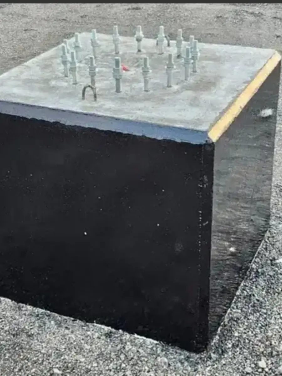
The connection between the pole and the foundation is the anchor-bolt assembly, and it is the most sensitive load-transfer point in the entire structure. The pole base plate is fixed onto a group of bolts cast into the concrete in a specific pattern matching the plate holes, and these bolts are commonly specified to ASTM F1554, which defines the strength grades and material properties of anchor bolts. It is not enough for the pole to be sound and the concrete strong if the bolt pattern, grade or embedment depth in the concrete does not match the pole's actual moment; a bolt weaker than the load, or insufficiently embedded, or lacking corrosion protection at the ground line, becomes the weakest link from which failure begins despite everything above and below it being sound.
After the pole is set on its bolts comes the levelling grout beneath the base plate, which ensures that the compressive load transfers evenly from the plate to the foundation rather than being concentrated on the bolts alone. Deficient or voided grout leaves a gap under the plate, so the bolts carry a load they were not designed to bear alone and a slight movement is permitted that grows into tilt and cyclic stress. For this reason the base detail is executed per the design: a matching bolt pattern, a grade and material conforming to the specification, sufficient embedment in the concrete, sound levelling grout, and tightening to the specified tension torque in a crosswise sequence. These small details at the connection are what make a sound pole and a sound foundation work together as a single system.
Corrosion protection of the bolts is no less important than their mechanical strength, because the part exposed above the concrete sits in the very zone most attacked at the ground line. A bolt that corrodes at its neck loses its effective section under load exactly as the pole does, and becomes the weakest link even if its grade was adequate on supply. For this reason the connection as a whole — plate, bolts, levelling grout and concrete — is treated as a single detail that must reach the same design life required of the pole, not a secondary accessory added after the design is complete.
Reading the Signs: What Each Failure Mode Shows Early
Because the three mechanisms begin small and advance before reaching the critical threshold, each has an early sign that can be spotted visually if one knows where to look. Base corrosion appears as a band of rust or a bulge in the coating precisely at the ground line, or as the galvanized surface turning a coarse grey that indicates the zinc layer is nearing depletion, with particular concentration at the zone adjacent to the concrete and around the service door. Fatigue shows as a fine hairline crack beginning at the base weld toe or at the corners of the door opening — the most concealed and most dangerous sign, because it may not be seen without cleaning the location and inspecting it closely. Foundation movement appears as a newly developed tilt in the pole's verticality, or cracking and crumbling in the concrete neck, or a bolt showing signs of loosening or rust.
The essential difference between this guide and a maintenance programme is that the purpose here is not to schedule inspection but to link the sign to its mechanism: a band of rust at the base means the corrosion-protection system is being breached and needs immediate local repair before the section is reduced; a hairline crack at a weld means the fatigue mechanism has actually begun and warrants an engineering assessment, not a surface repair; a newly developed tilt means the foundation or the connection has moved and the bolts and concrete must be inspected before treating the pole. Reading the sign in the light of its mechanism is what turns inspection from a passing observation into a diagnosis that directs the correct intervention; the scheduling and repair details are addressed by the dedicated maintenance guide.
Failure Mode and Warranty: Where the Line of Responsibility Falls
Understanding the failure mechanism is not an abstract engineering exercise; it is what determines where responsibility falls. Aktar Lighting Poles Est. issues a manufacturer warranty of up to ten years, and it is a ceiling, not a floor: each item has its own independent term fixed in the quote and purchase order, and 'up to ten years' does not mean every item is warranted for ten. The warranty covers defects attributable to manufacturing in three items: the pole structure with its manufacturing and weld defects, hot-dip galvanizing to ISO 1461, and powder coating. In the language of failure mechanisms, a fatigue crack arising from a weld defect attributable to manufacturing, or early corrosion caused by a flaw in the galvanized layer before its term elapses, both fall within the scope of a defect attributable to manufacturing.
By contrast, the manufacturer warranty does not cover poor installation by a third party or installation contrary to instructions, nor accidents and impact, nor unauthorised modification of the pole or its foundation, nor force majeure. In the language of the same mechanisms: a pole that tilted because the foundation was cast deficiently or the bolts were torqued incorrectly on site is a failure originating in installation, not manufacturing, and corrosion that began from a scratch caused by an impact on site is impact damage, not a galvanizing defect. Also expressly excluded is everything relating to luminaires, floodlights and LED sources, which are made by specialist suppliers and carry the original supplier's own warranty, not the pole's manufacturer warranty. For this reason the failure mode is documented when it occurs: diagnosing it precisely is what places each case in its correct category among manufacturing, installation and use.
Frequently asked questions
Where is a lighting pole most likely to fail?
The ground-line zone — from just above ground level to just below it — is the most dangerous location on the pole. Trapped moisture, salts and wet-dry cycling converge there and accelerate corrosion, and it is at the same time the section where the wind-induced bending moment is at its maximum. When the most severe corrosion meets the greatest stress at the same place, the ground line becomes the primary point of failure, which is why the heaviest lines of protection are directed at it.
Why is powder coating alone not enough to protect a pole from rust?
Powder coating is an organic layer for colour, appearance and additional protection, but on its own it is not a corrosion-protection system. Any scratch or porosity exposes the steel, and because the coating gives no cathodic protection, rust begins at the point of damage and creeps beneath the adjacent layer, lifting it. The system that prevents this is hot-dip galvanizing to ISO 1461 as the base — because it protects by both barrier and cathodic action and coats the inside of the tube — then coating over it for colour when required, not coating as a substitute for it.
What is fatigue and why is it considered more dangerous than failure under peak load?
Fatigue is a failure arising from the repetition of stress, not its magnitude alone. Wind oscillates the pole, so stress cycles accumulate over the years until a hairline crack initiates at a concentration point — usually at the base weld or the door-opening corners — and then grows until it crosses the section. Its danger is that it occurs at a stress far below the yield stress and is not preceded by a visible deformation to warn of it; the crack advances silently, which is why the Saudi Building Code SBC 301 and EN 40 treat wind as a dynamic load.
Does the manufacturer warranty cover a pole failure caused by a foundation or installation error?
No. The Aktar Lighting Poles Est. manufacturer warranty covers defects attributable to manufacturing in the pole structure and its welds, hot-dip galvanizing and powder coating, up to ten years with an independent term for each item fixed in the quote and purchase order. Failure arising from poor third-party installation, a wrongly cast foundation, an accident or impact, or unauthorised modification is excluded. Luminaires and LED sources are also excluded, as they carry their original supplier's own warranty.