Why earthing is a distinct safety decision, not a luxury
Lighting-pole earthing and the electrical safety tied to it are not a secondary detail appended at the end of a project; they are a standalone engineering decision that determines whether the metal pole is a safe neighbour to passers-by or a silent source of danger. A metal pole is an excellent conductor of current, so if insulation breaks down inside the luminaire or junction box without a sound earthing path, the pole body itself becomes live and may carry the full supply voltage to any hand that touches it. This hazard does not distinguish between a maintenance worker and a passing child, which is why earthing is treated as a requirement of life and not a supplementary item to be taken lightly.
This guide differs from our others in its angle: while the foundations and installation guide addresses the mechanical side of pole stability and load resistance, and the SASO/IEC road-lighting specifications guide addresses the photometric and electrical side of the luminaire and illumination levels, this guide focuses exclusively on the electrical safety chain — earthing, equipotential bonding, and protection against leakage, surge, and lightning. Separating these axes is necessary because success in one does not guarantee the others; a pole may be mechanically sound and perfectly lit while simultaneously being a lethal electrical hazard.
The most dangerous trait of earthing defects is that they are inherently hidden; a pole with deficient earthing lights up and operates entirely normally for months or years, and the defect surfaces only at the first insulation fault, first lightning strike, or first leakage current. At precisely that moment the protection system is supposed to intervene to cut the current or drain it safely to earth, and if it is deficient it turns a transient fault into an accident. Therefore the safety system is designed for the worst case, not for normal operation, and every numeric threshold mentioned in this guide must be verified against the latest edition of the standard, the project category, and a qualified engineer.
The earthing system: electrode, strip, and earth resistance
A lighting-pole earthing system consists, at its core, of an earth electrode driven into the soil, an earthing conductor connecting the pole body and junction box to that electrode, and sometimes an earthing strip or ring tying the line's poles together. The aim is to provide a low-resistance path to drain any fault or leakage current into the mass of earth, so that the pole body's voltage stays close to earth potential and does not create a dangerous potential difference for anyone touching it. The electrode — a copper or galvanised-steel rod or a plate — is chosen according to soil type, the depth of the moist layer, and the target resistance value.
The pivotal design value is the electrode's earth resistance; the lower it is, the faster, safer, and more reliably the current is drained and protection devices operate. This resistance is affected by soil type, moisture, salt content, electrode depth, and number of electrodes, so dry sandy soils — common in many regions of the Kingdom — may require deeper or multiple electrodes or soil treatments to lower the resistance to an acceptable level. The target resistance value is confirmed against the latest edition of the standard and the project authority's requirements, since thresholds vary by installation type and the presence or absence of lightning protection.
The system is completed not by design alone but by measurement and documentation; the earth resistance is actually measured after installation with a dedicated meter, and the values are recorded in a test report attached to the handover file. It is also noted that resistance varies seasonally with soil dryness or moisture, so measuring in the dry season gives a more realistic worst case. As we note in the foundations and installation guide, the earth electrode's position is coordinated with excavation of the concrete base early on, so the crew is not forced into improvised solutions after the concrete is poured.
IEC 60364 for the installation and luminaire protection Classes I and II
The IEC 60364 standard sets the general framework for low-voltage electrical installations, and from it the principles of protection against electric shock in outdoor lighting systems are derived. The standard distinguishes between basic protection — preventing contact with live parts through insulation and barriers — and fault protection, which intervenes when insulation breaks down, and here the role of earthing and automatic disconnection of supply comes in. Understanding this division is necessary because the metal pole usually sits in an outdoor area exposed to moisture and dust, an environment that raises the likelihood of insulation faults over time.
The classification of the luminaires themselves by protection method into classes — most prominently Class I and Class II — is defined in equipment standards such as IEC 60598 for luminaires (and at the general level in IEC 61140), while IEC 60364 governs how these classes are installed, earthed, and disconnected on site. In Class I, protection relies on bonding the exposed metal parts to the protective earthing conductor, so that if a fault occurs the current is drained to earth and the protective device operates; therefore sound earthing is an indispensable condition for the safety of this class's equipment. Class II, by contrast, relies on double or reinforced insulation so that it does not need protective earthing for exposed parts, and is sometimes used for luminaires to raise the safety margin, but it does not dispense with earthing the metal pole body itself.
The choice of class must not be understood as a substitute for earthing the lighting pole; even with a Class II luminaire, the metal pole body and its metal components still need bonding and earthing that ensure any incidental voltage finds a safe path. Reconciling the equipment class (per its equipment standard) with the earthing design and the means of automatic disconnection (per IEC 60364) is what achieves a coherent system. We always recommend that protection classes and disconnection methods be adopted according to the latest editions of the relevant standards, the operating authority's requirements, and under the supervision of a qualified engineer — not by field improvisation.
Lightning and surge protection per IEC 62305 and SPDs
Lighting poles, by virtue of their height and their standing in open spaces, are more exposed than others to direct lightning strikes and to electrical surges induced in supply lines. The IEC 62305 standard addresses lightning risk management and the design of protective measures, from assessing the risk level through current-drainage paths to protecting internal equipment. On highways, open areas, and tall lighting masts, this dimension becomes essential, and as we note in the stadium mast engineering guide, great height doubles the consideration from both the mechanical-load and lightning-exposure sides at once.
The most practical protective device at the pole level is the surge protection device (SPD), installed at the junction box to limit transient voltage surges caused by lightning or grid switching and drain them to earth before they reach the luminaire and its electronic driver. Because LED devices, their drivers, and control systems are sensitive to voltage surges, the absence of a suitable SPD shortens their life and increases their silent failures. The SPD's class and capacity are chosen according to the installation location and risk level, and these choices are confirmed against the standard and the risk assessment with a qualified engineer.
A distinction should be drawn between lightning protection and protective earthing; they are complementary but neither replaces the other. The lightning system drains very high, very short currents, while protective earthing deals with supply faults, and good integration between them requires tight equipotential bonding and sufficient earth electrodes to avoid dangerous potential differences at the moment of drainage. This dimension takes on special importance in camera and surveillance poles, which carry electronics and sensitive data cables, and in extended infrastructure projects where supply lines interlace over long distances.
IP ratings per IEC 60529 for junction boxes and luminaires
The IP rating, described in the IEC 60529 standard, defines the degree to which an enclosure prevents the ingress of solid objects and dust (first digit) and water (second digit), and it is among the most important factors in keeping the electrical safety system effective in the outdoor environment. The junction box behind the pole's service door and the luminaire at its top are exposed to dust, rain, road washing, and fluctuating humidity, and any weakness in sealing opens the door to moisture ingress that damages insulation, spoils connections, and leads to leakage faults over time. Therefore the required IP level for each component is set according to its location and exposure.
Naturally, the luminaire mounted at the pole top needs a high protection degree resisting full dust and falling or jetting water depending on location, while the junction box behind the service door needs sealing that guards against dust and moisture seeping through the door. In coastal and salty environments, which we address in the corrosion-resistant coastal lighting poles guide, the high IP requirement is paired with anti-corrosion requirements because salty moisture attacks both the enclosure and the connections. The required IP ratings for each component are confirmed against the standard and the actual site conditions.
The IP rating declared on paper is not enough if it is not maintained in installation and maintenance; it takes only a missing gasket, an improperly closed cover, or a cable entering without a proper gland for the sealing to fail in practice regardless of the nominal rating. For this reason a tightly sealed service door and a securely closed junction box are an integral part of the safety system, not a mere cosmetic detail. As we explain in the maintenance and pole lifespan guide, re-tightening seals and verifying gasket integrity is a periodic maintenance item that preserves protection effectiveness over the pole's life.
The RCD residual-current device and automatic disconnection
The residual-current device (RCD) is a device that monitors the balance of current entering and leaving the circuit, and if it detects a difference indicating current leaking to earth — such as passing through a human body or through collapsed insulation — it disconnects the supply in a very short time before the current reaches a harmful threshold. This device complements earthing and does not replace it; earthing provides the path, the RCD detects the leakage and cuts, and the automatic disconnection of supply function in IEC 60364 relies on the two working together with the overcurrent protective device. The absence of any of these elements weakens the entire chain.
The RCD type and sensitivity are chosen according to the load's nature and the installation environment; outdoor lighting circuits exposed to moisture may require a sensitivity suited to protecting people, bearing in mind that the natural leakage currents of LED drivers may cause nuisance tripping if the load is not calculated and the circuits not carefully distributed. This balance between effective protection and avoiding unjustified tripping requires deliberate engineering design rather than templated installation, and the sensitivity values and disconnection time are confirmed against the latest edition of the standard and with a qualified engineer.
On long road-lighting lines, protection is distributed across circuits so that a fault in a single pole does not switch off an entire stretch of road and leave a dark area. This deliberate distribution of circuits and protective devices links safety with the service continuity we address in the SASO/IEC road-lighting specifications guide. Balancing the segmentation of circuits to improve safety and continuity on one hand against the simplicity and maintainability of the system on the other is a design decision taken at the project level, not the individual pole.
Equipotential bonding, the service door, and the sealed junction box
Equipotential bonding is the principle of connecting all conductive metal parts in the pole — the pole body, the service door, the connection panel, and any adjacent metal structure — with a conductor that brings them all to the same potential. The benefit is that it prevents a dangerous potential difference from arising between two metal parts a person might touch simultaneously at the moment of fault or lightning, eliminating the current path through the body. This bonding complements protective earthing and is a pillar in protecting maintenance workers who open the service door and deal directly with the internal components.
The pole's service door is not merely a mechanical opening but a sensitive access point for electrical safety; it protects the junction box from tampering and unauthorised access, must itself be bonded into the equipotential system, and must close tightly to preserve the internal IP rating. The junction box behind it houses the protective devices, earthing connections, and terminals, and must be orderly, labelled, and sealed against moisture, for a chaotic or open box is a common source of leakage faults and accidental contact with live parts.
These details, which may seem secondary, are in fact the daily interface of safety; most contacts and accidents occur at this access point during operation and maintenance, not at the distant pole top. Therefore the service door and junction box are designed with care equal to that of the luminaire and base, and their periodic inspection is integrated into the preventive maintenance plan. As we note in the maintenance and pole lifespan guide, the continued integrity of equipotential bonding and the sealing of the junction box is what keeps the safety system effective throughout the years of service, not only on handover day.
Aktar: manufacturing poles with a coherent electrical safety system
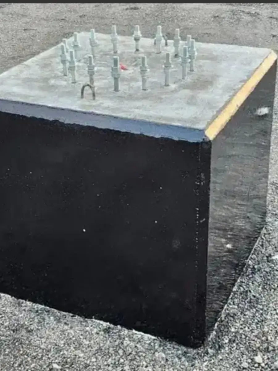
At Aktar, every pole is manufactured in our factory in the Al-Sulai district of Riyadh with the electrical safety system treated as an integral part of the design rather than a later addition; we provide a tightly sealed service door and a junction box prepared to accommodate protective devices, earthing points, and equipotential bonding means, and we provide an earthing point on the pole body to ease connecting the earth electrode on site. Our seven families include street, decorative, garden, sports, laser-cut, walkway and parking, and bollard poles, in addition to concrete bases, all manufactured to a specification that accommodates the project's electrical safety requirements.
Our poles are hot-dip galvanised per ISO 1461 then electrostatically powder-coated, and this surface sealing protects the pole from corrosion and safeguards the integrity of the internal electrical components against moisture. We design wind loads per the Saudi Building Code SBC 301 requirements, comply with SASO requirements and the ISO 9001 quality management system, and manufacture to specification in heights from 0.5 to 16 metres and higher on request, with the pole prepared to accommodate surge protection devices and supply cables as defined by the project engineer. We supply all regions of the Kingdom with a typical delivery time of 7 to 14 business days, have documented projects in the government and private sectors, and offer a manufacturer warranty of up to ten years per the specification.
We affirm that the final earthing and protection system design — earth resistance values, the selection of RCDs and SPDs, IP ratings, and protection classes — is always adopted against the latest edition of the standards, the operating authority's requirements, and under the supervision of a qualified engineer on site, and that our role is to provide a pole manufactured to specification that accommodates this system safely. We are pleased to offer a free, non-binding preliminary technical consultation to discuss your project's requirements and align them with the pole design; contact us via WhatsApp and we will be glad to help.
Frequently asked questions
Why is earthing of lighting poles necessary for electrical safety?
A metal pole is an excellent conductor of current, so if insulation breaks down inside the luminaire or junction box without a sound earthing path, the pole body becomes live and may carry the supply voltage to anyone touching it. Earthing provides a low-resistance path that drains fault current to earth and enables protective devices to disconnect. Because the danger of deficient earthing is hidden and surfaces only at the first fault or lightning strike, earthing is treated as a requirement of life, not a supplementary item.
What is the difference between protection Classes I and II in lighting luminaires?
In Class I, protection relies on bonding the exposed metal parts to the protective earthing conductor so the fault current drains to earth, making earthing indispensable. Class II relies on double or reinforced insulation that needs no protective earthing for exposed parts. Even so, the metal pole body itself still needs bonding and earthing even with a Class II luminaire. Luminaire classes are defined in equipment standards such as IEC 60598, while IEC 60364 governs their installation and earthing on site, all adopted under the supervision of a qualified engineer.
Does an SPD protect the pole from lightning, and does it replace earthing?
A surge protection device (SPD) limits transient voltage surges from lightning or grid switching and drains them to earth before they reach the luminaire and its driver, and it is essential because LED electronics are sensitive to surges. But it does not replace protective earthing or the lightning system per IEC 62305; they are complementary elements, and good integration requires tight equipotential bonding and sufficient earth electrodes. The device's class is confirmed against the standard and the risk assessment.
What is the role of the RCD and the IP rating in pole safety?
The RCD monitors the current balance in the circuit and quickly disconnects the supply when it detects leakage to earth; it complements earthing and does not replace it within the automatic disconnection function of IEC 60364. The IP rating per IEC 60529 defines the prevention of dust and water ingress into the junction box and luminaire, and any sealing weakness damages insulation and causes leakage faults. The IP rating is maintained by sealing the service door and keeping gaskets intact during installation and maintenance.